Yes, the 261B6 has a dual primary and two center taps on the secondary. You will not need these. Put heat shrink on the ends to prevent any shorting and zip-tie them somewhere safe. Leave the full length for future expansion.
See the attached schematic I created for the racked version mention in another post on this forum.
How did you determine T1 is bad?
I really wouldn't recommend this if you not experienced with electronics. A skilled tech is the way to go. BUT, if you are set on doing it yourself I will provide some guidance.
1. Be sure to unplug the unit from the AC supply before doing anything. There are very high voltages inside that can hurt you. Momentarily short all four leads of C1 to ground to discharge any remaining voltage stored in the capacitor.
2. Be very careful with the wires coming out of the new transformer. They can easily become detached and a very difficult to repair. Get the new T1 securely mounted to the preamp chassis before doing anything with the wires.
3. Once you determine where you are mounting the new T1, drill the mounting holes and also dill a hole of sufficient size to pass the wires through to the inside of the chassis. Once you have the old T1 removed there will be two thru-holes exposed where the old screws were, this maybe a good place to drill since you already have a starter hole.
- use painters tape on the inside of the chassis to catch all the metal fillings created from drilling. Vacuum out the unit thoroughly. Any metal particles left loose inside the chassis can create major issues.
4. Fit a rubber grommet inside the hole to prevent the sharp metal edges of the hole from cutting through the wire then feed the wires into the chassis.
5. In the attached schematic, find T1 and recreate the specified wiring. I would cut the existing wires on the old T1 very close to transformer body and re-attach the new T1 wire to the old wires. Strip and tin your wires, form into a hook, slide a piece of heat shrink over the wire to cover the connection, join the two hooked wires, solder, move heat shrink into position and apply heat. Make sure no exposed wire is showing.
A. On the primary ("input") side of the new T1 connect:
Black to AC line
White to AC neutral
B. On the secondary side connect:
Red to rectifier (red)
Red to rectifier (red)
Green to hum adjust (green)
Green to hum adjust (yellow)
6. A safe test would be unsolder the rectifier output from C1A, power the unit on and measure the voltage out of the rectifier, which should be somewhere around 270VDC. This will protect the rest of the circuit from damage in case you made a mistake somewhere. If it was me I would bring the power up slowly using a variac, but that is an extra precaution and not mission critical.
Again, if this was me, I'd replace the rectifier and all the electrolytic caps. This will reduce noise and make your unit last for several more decades. Plenty of folks have these all original and I'm sure they sound fine but after upgrading to a modern power supply the improvements are very noticeable. Caps fail slowly (typically) and it can be difficult to detect just how much this slow failure is effecting performance.
There are plenty of ways to screw this up and only one way to get it right! Good luck, be careful, double check everything.
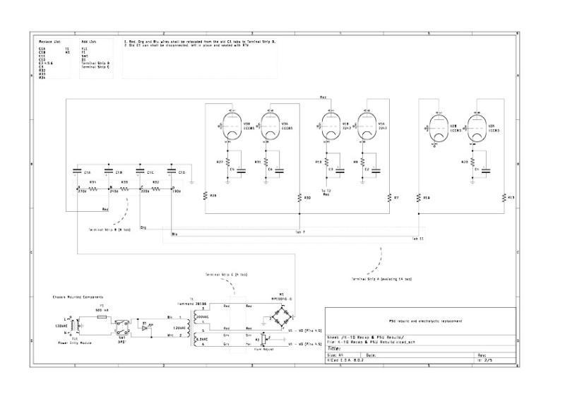
- K10 PSU.jpg (67.59 KiB) Viewed 14728 times